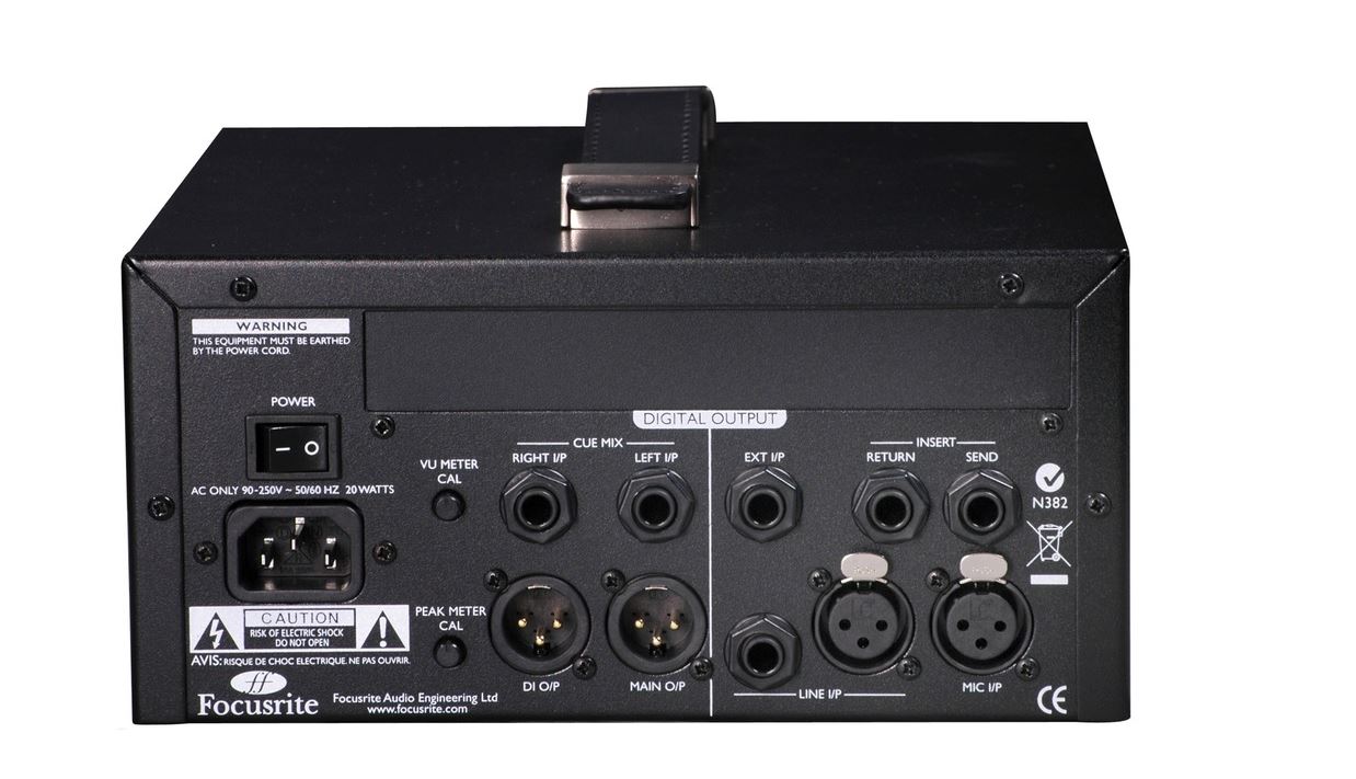
Analogue Channel Inputs
- XLR Mic input
- One XLR and one TRS line input
- XLR Instrument input TRS Jack
- External ADC input TRS Jack
- TRS jack return
Analogue Channel Outputs
- TRS jack send
- XLR balanced line output
- XLR DI output
- TS jack DI through
Analogue Channel Additional I/O
- TRS Jack cue mix left input
- TRS Jack cue mix right input
- 1/4” TRS Jack headphones output
Mic Input Response
- Gain range : 0dB to 60dB in 10dB steps + 20 dB of variable gain
- Input Impedance : Switched Impedance setting Equivalent Input Impedance at 1kHz
- Low = 600 Ohms
- ISA110 = 1400 Ohms
- Med = 2400 Ohms
- High = 6800 Ohms
- EIN (Equivalent Input Noise) : -126dB measured at 60dB of gain with 150 Ohm terminating impedance and 22Hz/22kHz band-pass filter
- Noise : Noise at output with unity gain (0 dB) and 22 Hz-22 kHz band pass filter -97 dBu
- Signal-to-Noise Ratio : 106 dB relative to max headroom (9dBu)
- Total Harmonic Distortion : + Noise Measured at medium gain (30dB) with a 1kHz -20dBu input signal and with a 22Hz/22kHz band-pass filter < 0.0009%
- Frequency Response :
- At minimum gain (0 dB) -0.5dB down at 10Hz and -3dB down at 125kHz
- At maximum gain (60dB) -3dB down at 16Hz and -3dB down 118kHz
- CMRR (Common Mode Rejection Ratio) : 98dB (Channel 1, 1kHz, maximum gain with +24 dBu input)
- Crosstalk Channel to Channel : With 10dB@1kHz input to chA, chB output =104dBrA. With 10dB@10kHz input to chA, chB output = 84dBrA
Line Input Response
- Gain range : -20dB to +10dB in 10dB steps + 20 dB of variable gain
- Input Impedance : 10 kΩ from 10 Hz to 200 kHz
- Noise : Noise at main output with gain at unity (0 dB) measured with 50 Ω source impedance and a 22Hz - 22 kHz band pass filter
- Signal-to-Noise Ratio : Measured with a 22 Hz-22 kHz band pass filter
- 120 dB relative to max headroom (24 dBu)
- 118dB relative to 0dBFS (+22dBu)
- Total Harmonic Distortion : + Noise Measured with a 0 dBu input signal, and a 22 Hz-22 kHz band pass filter
- Frequency Response : At unity gain (0 dB)
- -0.3dB down at 10Hz and -3dB down at 200kHz
Instrument Input Response
- Gain range : 10dB to 40dB continuously variable
- Input Impedance :
- High = greater than 1M
- Low =greater than 300k
- Noise : Measured with 22 Hz-22 kHz band pass filter
- Minimum gain (+10 dB): -92 dBu
- Maximum gain (+40dB): -62dBu
- THD : At minimum gain (+10)
- Frequency Response :
- At minimum gain (+10 dB) -10dB input: 10Hz-100kHz +/- 0.6dB
- At maximum gain (+40 dB) -40dB input: -2.5dB down at 10Hz and 0dB at 100kHz
Meters
- Moving Coil (MC) Meter : factory calibrated to 0VU = +4dBu with 1kHz sinewave. With the VU Cal button pressed the meter can be adjusted on the rear panel to allow 0VU to equal +10dBu to +26dBu with the centre detent being equal to +22dBu.
- Peak LED Meters : Calibrated in the detent position for 0dBFS = +22dBu, calibration is adjustable on the rear panel to allow 0dBFS to equal +10dBu to +26dBu
Routing for MC and Peak1 meter is after the HPF, pre insert send or switched post insert return. Peak2 is always pre ADC channel 2, which can be fed by external input or Instrument input.
- LED Levels : As follows, when peak calibration is set to center detent on the rear panel. (This is when using the internal ADC). 0 = +22dBu
- -2 = +20dBu
- -6 = +16dBu
- -12 = +10dBu
- -18 = +4dBu
- -42 = -20dBu
- Frequency Response :
- At minimum gain (+10 dB) -10dB input: 10Hz-100kHz +/- 0.6dB
- At maximum gain (+40 dB) -40dB input: -2.5dB down at 10Hz and 0dB at 100kHz
High-Pass Filter
- Roll-Off : 18 dB per octave (3 pole filter)
- Frequency : Fixed 75Hz measured at the 3dB down point
Weight and Dimensions
- W x D x H :
- 220mm (W) x 104mm (H) x 254 - 290mm (D - top to bottom)
- 8.66" (W) x 4.1" (H) x 10" - 11.4" (D - top to bottom)
- Weight 3.9 kg 8.6 lbs